background image
Frame Relay Protocols 541
Figure 8-13
Hybrid of Full and Partial Mesh
Two options exist for Layer 3 addressing in this case. The first is to treat each VC as a separate
Layer 3 group; five subnets and five IPX networks would be needed for the Frame Relay
network. However, if Routers A, B, and C are considered alone, they meet the criteria that each
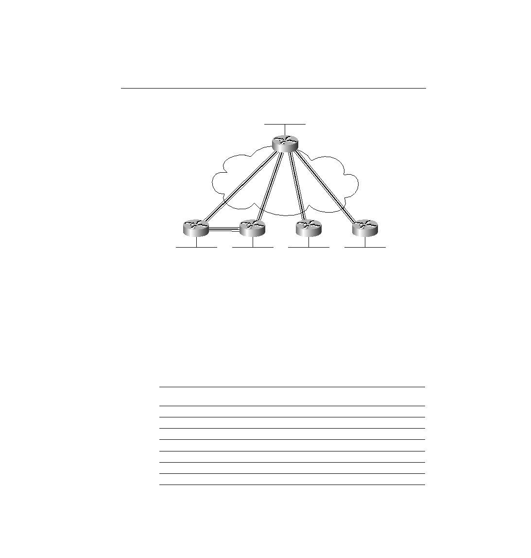
can send packets directly to each other, like a full mesh. This would allow Routers A, B, and C
to use one subnet and IPX network. The other two VCs--between A and D, and between A and
E--are treated as two separate Layer 3 groups. The result is a total of three subnets and three
IPX network numbers.
To accomplish either style of Layer 3 addressing in this third and final case, subinterfaces are
used. Point-to-point subinterfaces are used when a single VC is considered to be all that is in
the group. Multipoint subinterfaces are used among Routers A, B, and C in Figure 8-13. The
section "Frame Relay Configuration," later in the chapter, provides full configurations for all
three cases illustrated in Figure 8-11, Figure 8-12, and Figure 8-13. Table 8-15 summarizes the
addresses and subinterfaces used.
Table 8-15
IP and IPX Addresses, and Point-to-Point and Multipoint Subinterfaces
Router
Subnet
IP Address
IPX
Network
IPX Address
Subinterface
Type
A
140.1.1.0/24
140.1.1.1
1
1.0200.aaaa.aaaa
Multipoint
B
140.1.1.0/24
140.1.1.2
1
1.0200.bbbb.bbbb
Multipoint
C
140.1.1.0/24
140.1.1.3
1
1.0200.cccc.cccc
Multipoint
A
140.1.2.0/24
140.1.2.1
2
2.0200.aaaa.aaaa
Point-to-point
D
140.1.2.0/24
140.1.2.4
2
2.0200.dddd.dddd
Point-to-point
A
140.1.3.0/24
140.1.3.1
3
3.0200.aaaa.aaaa
Point-to-point
E
140.1.3.0/24
140.1.3.5
3
3.0200.eeee.eeee
Point-to-point
A
DLCI 501
B
DLCI 502
C
DLCI 503
D
DLCI 504
E
DLCI 505
ch08.fm Page 541 Monday, March 20, 2000 5:17 PM