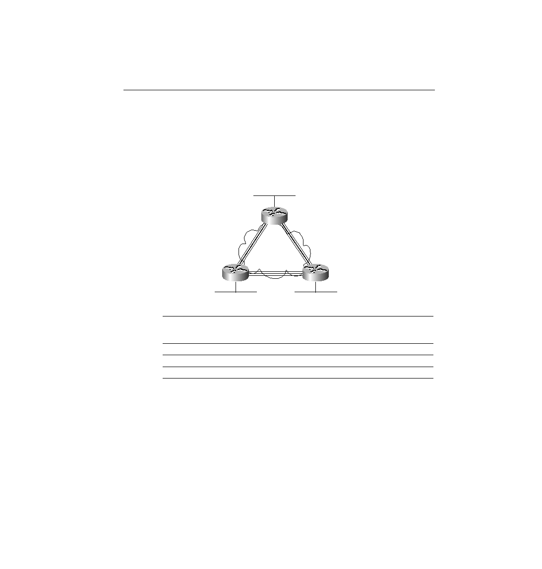
starts the first case with an illustration of a fully meshed Frame Relay network. In a full mesh,
each router has a direct connection to every other router, allowing the Frame Relay cloud to be
treated as one Layer 3 network. Figure 8-11 also shows IPX and IP addresses. The IPX and IP
addresses would be configured as subcommands on the serial interface. Table 8-13 summarizes
the addresses used in Figure 8-11.
routers do not have VCs to each other, each VC uses a different set of Layer 3 groups. Table
8-14 shows the IPX and IP addresses for the partially meshed Frame Relay network illustrated
in Figure 8-12. The addresses would be configured as subcommands on the serial interface.
(Note: The notation /24 signifies a subnet mask with 24 binary 1s--in other words,
255.255.255.0.)
Frame Relay
Interface
Frame Relay
Interface
192.0020.AAAA.AAAA
199.0020.CCCC.CCCC
199.0020.BBBB.BBBB