Frame Relay Protocols 537
Figure 8-9
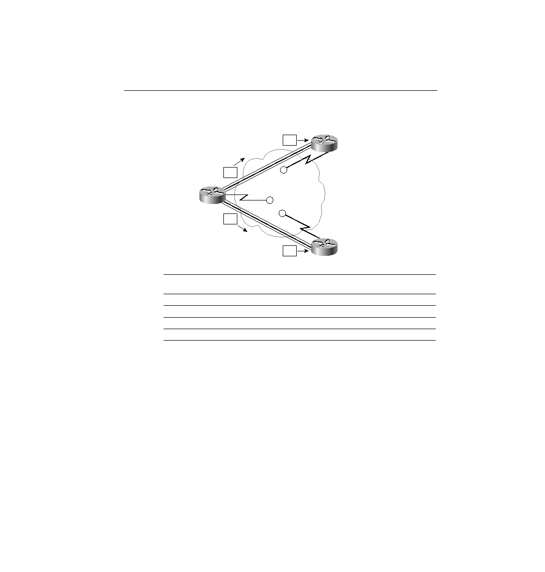
Frame Relay Global Addressing Convention, with Reality of Local Addressing
Figure 8-9 shows a frame being sent from Router A to Router B in one case, and to Router C in
the other case. As Router A sends a frame with DLCI 41, the Frame Relay switches send the
frame toward Router B. Before being sent on the access link to Router B, the final switch
changes the DLCI to 40 so that Router B knows who sent the frame. Similarly, Router A sends
a frame with DLCI 42, and it is received by Router C with DLCI 40.
In fact, the DLCIs used match the sample network with local addressing of Figure 8-8. In
essence:
·
Local addressing is how Frame Relay addressing works. However, by following the
convention of global addressing, planning is easier because the addressing appears similar
to LAN addressing.
·
A global address for one DTE simply means that all other DTEs with a VC to this one
DTE use its global address on their local access links.
Table 8-12
DLCI Swapping in Frame Relay Cloud
Frame Sent by
Router . . .
With DLCI Field
Is Delivered to
Router . . .
With DLCI Field
A
41
B
40
A
42
C
40
B
40
A
41
C
40
A
42
S
S
S
40
40
42
A
B
C
Global
DLCI 41
Global
DLCI 42
41
Global
DLCI 40
ch08.fm Page 537 Monday, March 20, 2000 5:17 PM