However, the values shown in Figure 8-7 are also valid. In practice, the style shown in Figure
8-8 is the typical choice, but it seems to be a bit more confusing. But why? The answer lies in
a term called global addressing
DLCI value on each end of the VC. Global addressing allows you to think of the Frame Relay
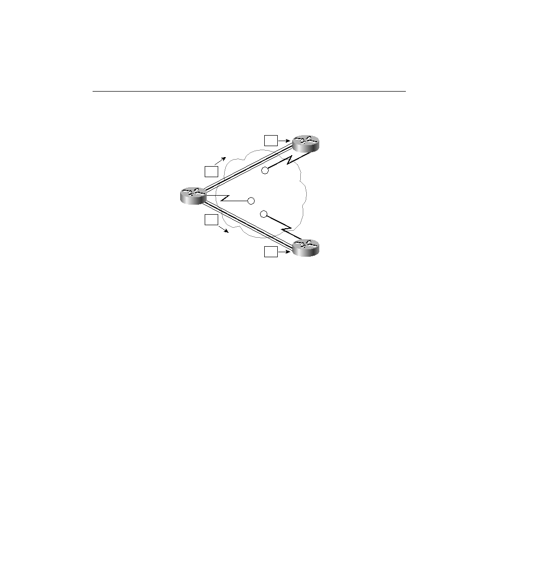
network like a LAN in terms of addressing concepts. Consider Figure 8-9, with the DLCI values
shown. In this figure, think of the DLCI values as an address for the DTE, which is similar to
how a unicast MAC address represents a LAN card.
address as the destination. Similarly, if Router B wants to send a frame to Router A, then Router
B (by the convention of global addressing) sends a frame with Router A's global DLCI value in
the header. Likewise, Router C sends frames with DLCI 40 to reach Router A, by convention.
Router A sends frames with DLCI 41 to reach Router B, and with DLCI 42 to reach Router C,
again, by the convention of global addressing. Figure 8-9 shows the DLCIs used for global
addressing and the actual values placed into the Frame Relay headers for correct delivery across
the network. Table 8-12 summarizes the DLCIs used in the figure.