Answers to Scenario 5-3: IP Subnet Design with a Class C Network 345
Figure 5-51
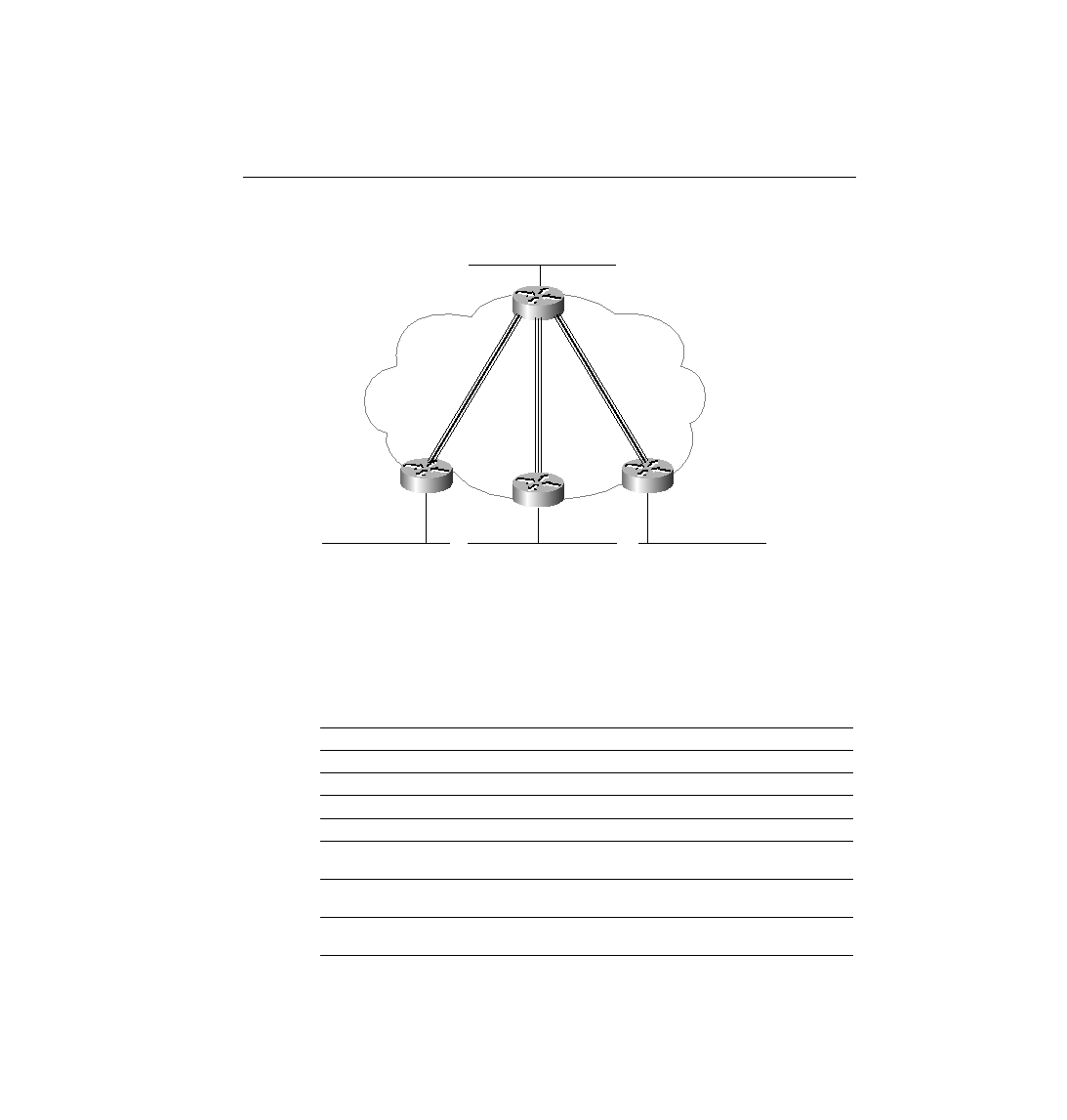
Scenario 5-3 Network, with Subnets Written on Diagram
Answers to Task 2 for Scenario 5-3
Given the design criteria and the network setup illustrated in Figure 5-45 for Scenario 5-3, Table
5-51 shows the choices of subnets and addresses in this example. Only one subnet, 200.1.1.224,
which is the broadcast subnet, is not used. Of course, you could have chosen a different
set of subnets and used them on different links, but the mask you used should have been
255.255.255.224, based on the criteria to maximize the number of hosts per subnet.
Table 5-51
Scenario 5-3 Addresses and Subnets
Location of Subnet
Subnet Mask
Subnet Number
Router's IP Address
Ethernet off Router A
255.255.255.224
200.1.1.32
200.1.1.33
Ethernet off Router B
255.255.255.224
200.1.1.64
200.1.1.65
Ethernet off Router C
255.255.255.224
200.1.1.96
200.1.1.97
Ethernet off Router D
255.255.255.224
200.1.1.128
200.1.1.129
VC between A and B
255.255.255.224
200.1.1.0
200.1.1.1 (A) and .2
(B)
VC between A and C
255.255.255.224
200.1.1.160
200.1.1.161 (A) and
.162 (B)
VC between A and D
255.255.255.224
200.1.1.192
200.1.1.193 (A) and
.194 (B)
A
Frame Relay
Partial Mesh
s0
s0
B
Subnet 200.1.1.64
Subnet 200.1.1.96
Subnet 200.1.1.128
Subnet 200.1.1.32
Subnet 200.1.1.160
Subnet 200.1.1.192
Subnet 200.1.1.0
C
D
s0
s0
ch05.fm Page 345 Monday, March 20, 2000 5:06 PM