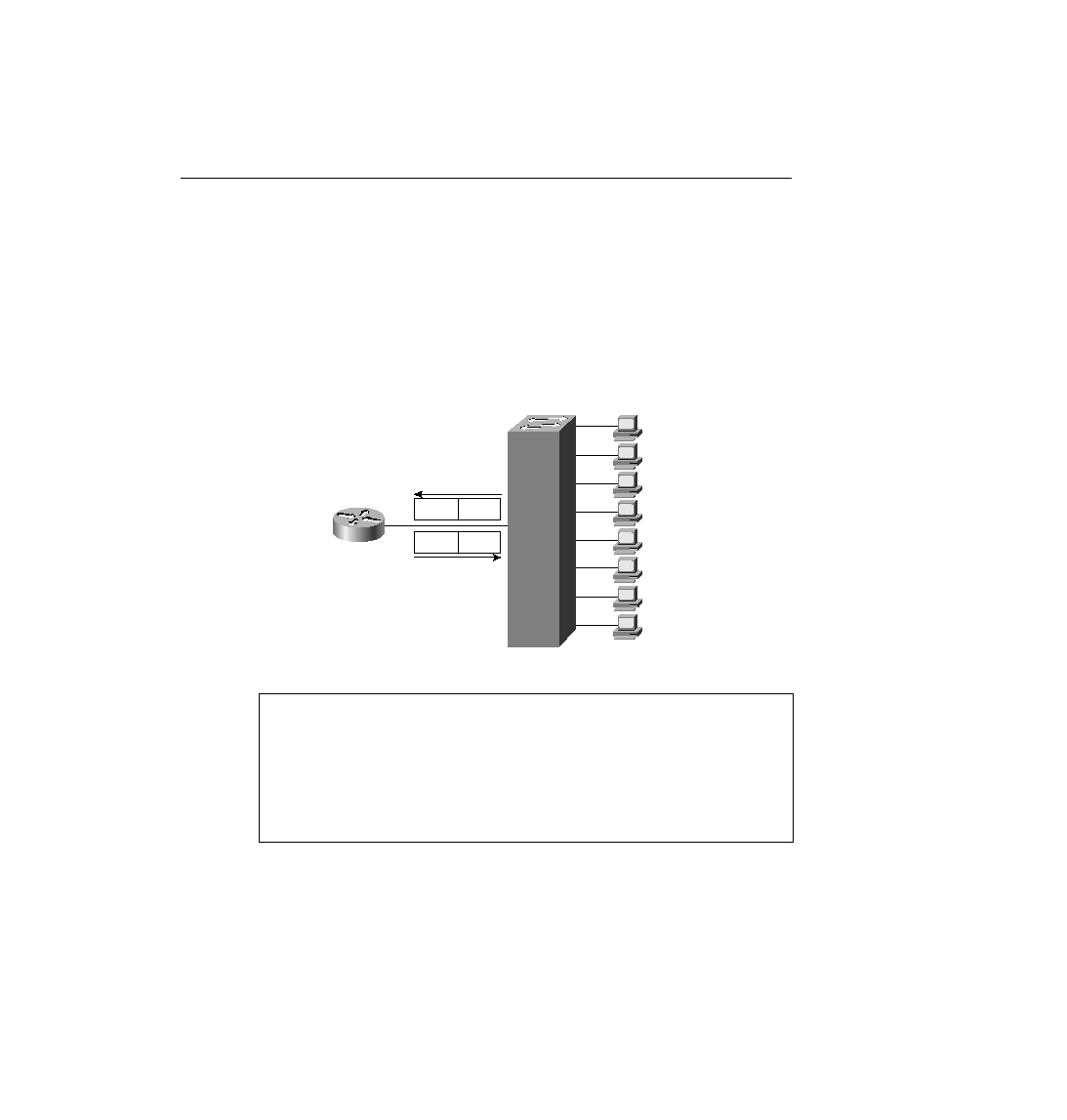
shows the router with a single interface and a single connection to Switch 2. The same tagging
method used between switches is used for frames sent to the router so that the router knows
from which VLAN the frame originated. For frames that the router routes between the two
VLANs, the incoming frame is tagged with one VLAN ID, and the outgoing frame is tagged
with the other VLAN ID by the router before sending the frame back to the switch. Figure 4-25
shows an example network, with flows from VLAN 1 to VLAN 2. The BPDU field also is used
to identify whether the encapsulated frame is a CBPDU. Example 4-1 shows the router
configuration required to support ISL encapsulation and forwarding between these VLANs.
router. Each is assigned an IP address because the interface is actually a part of three broadcast
domains, implying three IP subnets. The encapsulation command numbers the VLANs, which
must match the configuration for VLAN IDs in the switch.
ip address 10.1.1.1 255.255.255.0
encapsulation isl 1
!
interface ethernet 0.2
ip address 10.1.2.1 255.255.255.0
encapsulation isl 2
!
interface ethernet 0.3
ip address 10.1.3.1 255.255.255.0
encapsulation isl 3