174 Chapter 4: Bridges/Switches and LAN Design
Implementing VLANs with multiple switches adds more complexity that is not necessarily
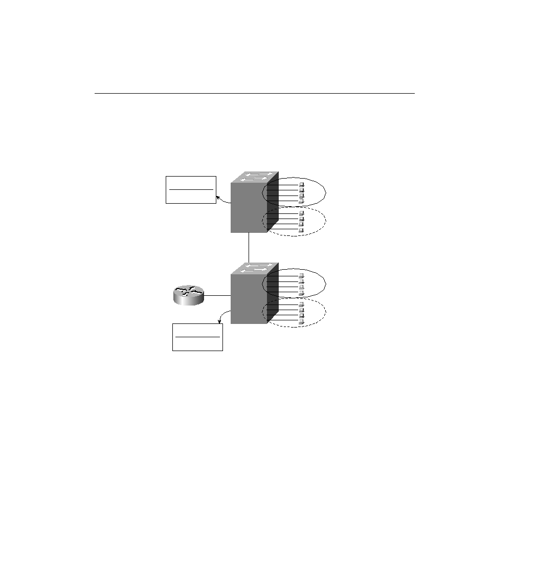
obvious. Consider Figure 4-23, which uses two switches connected with a Fast Ethernet. Two
VLANs are configured.
Figure 4-23
Two Switches, Two VLANs
The address table for VLAN1 lists the only two MAC addresses being used in VLAN1.
Consider a frame sent from PC11 to PC12:
Step 1
PC11 generates the frame, with destination MAC
0200.1111.0002.
Step 2
Switch 1 receives the frame on port E1.
Step 3
Switch 1 performs address table lookup in VLAN1's address table
because incoming port E1 is in VLAN1.
Step 4
Switch 1 forwards the frame out its E10 port.
Step 5
Switch 2 receives the frame in its E11 port.
At this point in the logic, everything seems straightforward. In the next step, however, several
choices could have been made by those who created the protocols used for LAN switching. The
choices for how Switch 2 could react to the incoming frame are as follows:
Address Table,
VLAN1
0200.1111.0001 E11
0200.1111.0002 E1
Address Table,
VLAN1
SW1
E1
E8
E10
E11
SW2
0200.1111.0001
0200.2222.0001
0200.1111.0001 E1
0200.1111.0002 E10
PC11
VLAN1
VLAN2
VLAN1
VLAN2
PC21
E1
E8
0200.1111.0002
0200.2222.0002
PC12
PC22
ch04.fm Page 174 Monday, March 20, 2000 5:02 PM