block, which is the goal. Both ports on Bridge 1 will be in a forwarding state. The interface in
which the other bridges receive their lowest-cost CBPDU about the root is considered to be
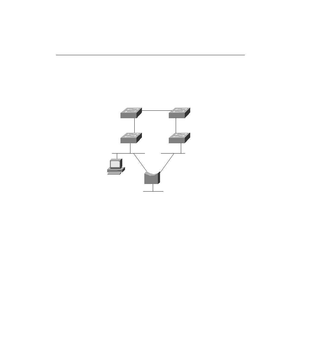
their root port. Figure 4-18 shows the root ports with a simple designation of RP.
nonroot ports. Each LAN has one bridge that is sending the CBPDU about the root with the
least cost. Referring to Figure 4-17, the segment to which Bridge 3 and Bridge 4 are attached
shows Bridge 4 advertising the lower cost (110). Bridge 4 is then considered to be the
designated bridge on that LAN segment, so Bridge 4 places its E0 port into forwarding state.
On the other LAN segments, only one bridge is sending CBPDUs, so it is obvious which bridge
will be designated bridge on each of those segments--Bridge 2's E1 port and Bridge 5's E1 port
will be placed into forwarding state as well.
interface. Table 4-11 outlines the state of each port and shows why it is in that state.