160 Chapter 4: Bridges/Switches and LAN Design
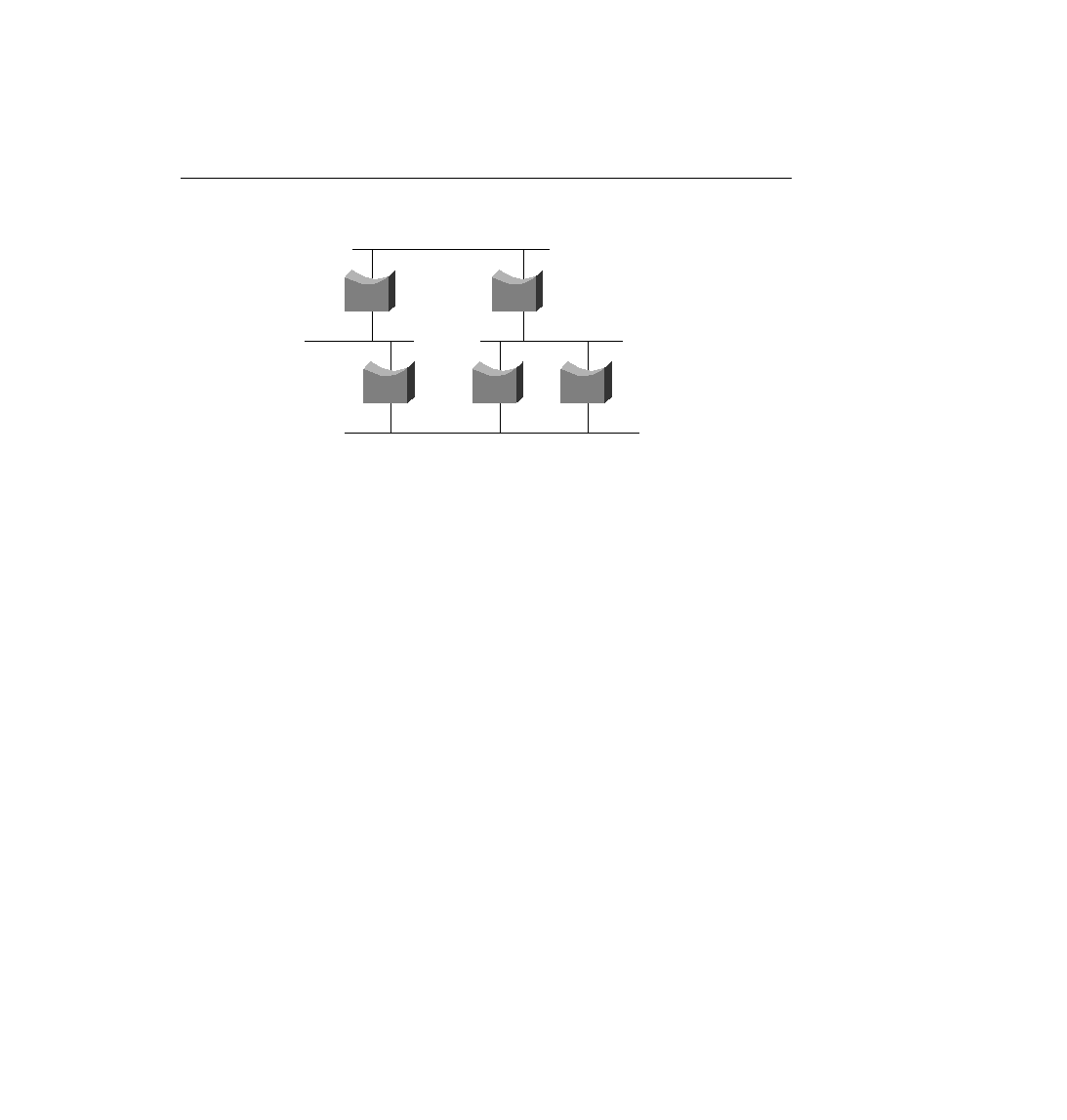
Figure 4-15
Looping and Frame Replication
To sum up, the benefits of the Spanning-Tree Protocol are as follows:
·
Physically redundant paths in the network are allowed to exist and be used when other
paths fail.
·
Bridging logic is confused by multiple active paths to the same MAC address; Spanning-
Tree Protocol avoids this by creating only one path.
·
Loops in the bridged network are avoided.
How the Spanning-Tree Protocol Works
The Spanning-Tree Algorithm results in each bridge interface being placed into either a
forwarding state or a blocking state. Interfaces in forwarding state are considered to be in the
current Spanning Tree; those in blocking state are not considered to be in the tree. The algorithm
is elegant but basic. Figure 4-16 illustrates a network with physical redundancy, which will need
to use STP.
The setup in Figure 4-16 uses four switches (B1, B2, B3, and B5) and one transparent bridge.
A variety of bridges and switches are shown to make the point that both Ethernet switches and
transparent bridges use Spanning Tree.
The key to the algorithm is that the set of all forwarding interfaces (those in the tree) form one
path through the LAN segments (collision domains), assuming that at least one physical path is
available. Three criteria are used to place an interface into forwarding mode:
·
All interfaces on the root bridge are in forwarding state.
·
Each nonroot bridge considers one of its ports to have the least administrative cost
between itself and the root bridge. This interface, called that bridge's root port, is placed
into a forwarding state.
·
Many bridges can attach to the same segment. These bridges advertise Configuration
Bridge Protocol Data Units (CBPDUs) declaring their administrative cost to the root
1
2
3
4
5
ch04.fm Page 160 Monday, March 20, 2000 5:02 PM