148 Chapter 4: Bridges/Switches and LAN Design
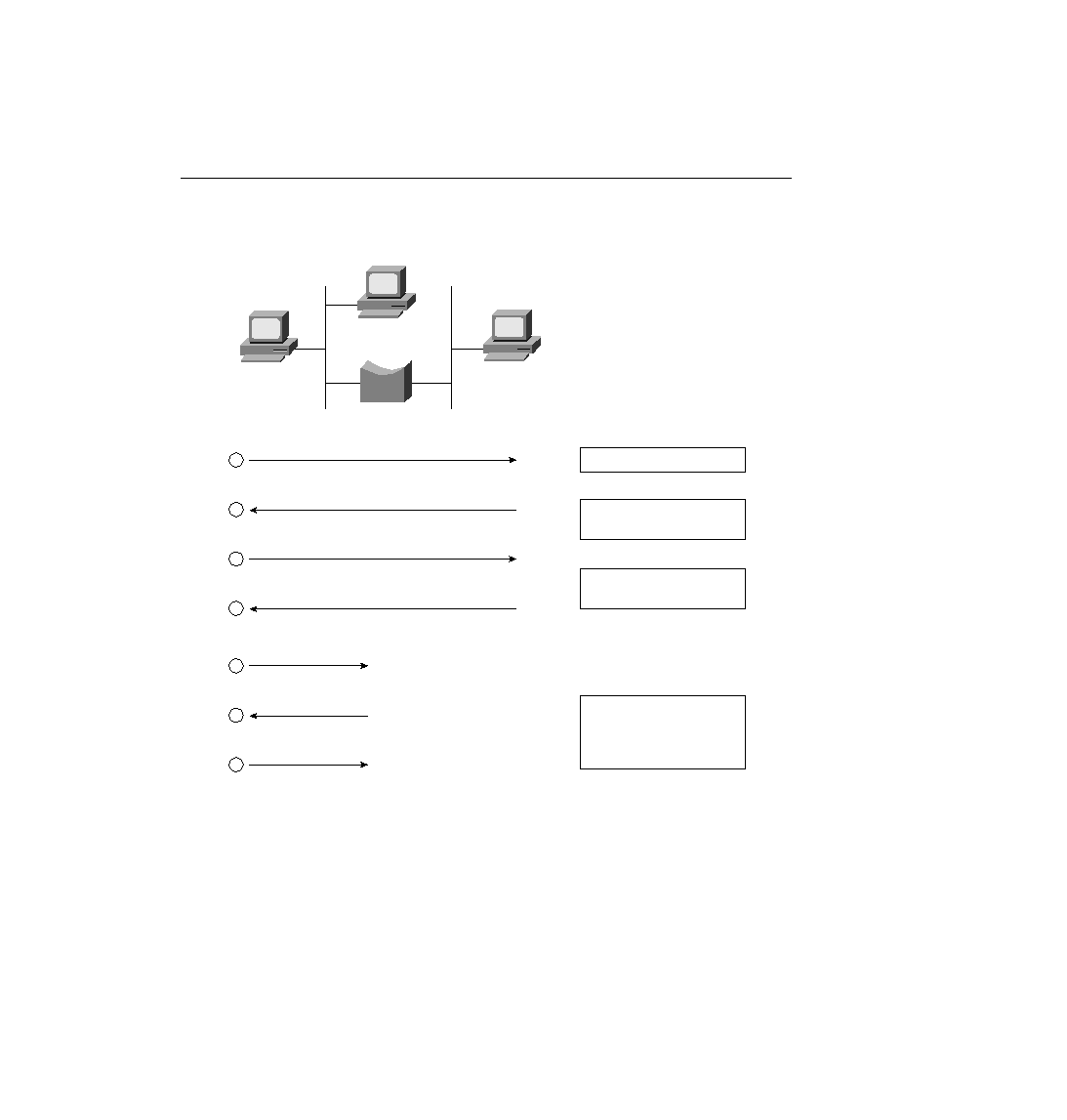
Figure 4-7
Example Protocol Flows--Using a Transparent Bridge
LAN Switching
An Ethernet switch appears to use the same logic as a transparent bridge. However, the internal
logic of the switch is optimized for performing the basic function of choosing when to forward
and when to filter a frame. Just as with a transparent bridge, the basic logic of a LAN switch is
as follows:
Step 1
A frame is received.
Step 2
If the destination is a broadcast or multicast, forward on all ports.
0200.3333.3333
Web
Client
E0
E1
DNS
DMAC = FFFF.FFFF.FFFF
SMAC = 0200.1111.1111
0200.1111.1111
E0
Address Table After Step 1
ARP (DNS)
0200.1111.1111
1
DMAC = 0200.1111.1111
SMAC = 0200.2222.2222
ARP
2
DMAC = 0200.2222.2222
SMAC = 0200.1111.1111
DNS Request
3
DMAC = 0200.1111.1111
SMAC = 0200.2222.2222
DNS Reply
4
DMAC = FFFF.FFFF.FFFF
SMAC = 0200.1111.1111
ARP (Web)
5
DMAC = 0200.1111.1111
SMAC = 0200.3333.3333
ARP
6
DMAC = 0200.3333.3333
SMAC = 0200.1111.1111
Connect to Web
7
0200.2222.2222
0200.1111.1111
E0
0200.2222.2222
E1
Address Table After Step 2
0200.1111.1111
E0
0200.2222.2222
E1
Address Table After Step 3
0200.1111.1111
E0
0200.2222.2222
E1
0200.3333.3333
E0
Address Table After Step 6
ch04.fm Page 148 Monday, March 20, 2000 5:02 PM