OSI Network Layer Functions 105
Figure 3-18
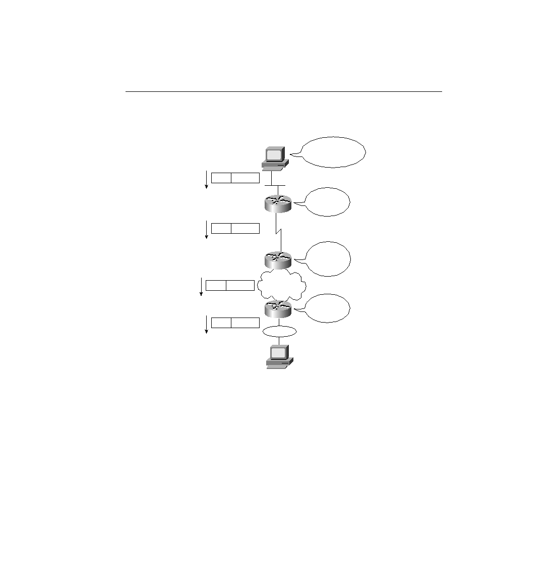
Routing Logic and Encapsulation--PC1 Sending to PC2
The logic behind the earlier three-step routing process is described in the following steps. Steps
A and B that follow describe the first of the three routing steps in this example. Steps C, D, E,
F, and G correspond to Step 2. Finally, Step H corresponds to routing Step 3.
Step A
PC1 needs to know its nearby router. PC1 first knows of R1's IP
address by having either a default router or a default gateway
configured. The default router defined on some host is the router
to which that host forwards packets that are destined for subnets
other than the directly attached subnet. Alternatively, PC1 can
learn of R1's IP address using Dynamic Host Configuration
FR
PC1
PC2
R1
R2
R3
10.0.0.0
10.1.1.1
168.1.1.1
168.10.0.0
168.11.0.0
168.1.0.0
My route
to that group is
out Serial Link.
Send directly
to Barney.
My route
to that group is
out Frame
Relay.
Destination is in
another group; send
to nearby router.
Eth.
IP Packet
HDLC IP Packet
FR
IP Packet
TR
IP Packet
ch03.fm Page 105 Monday, March 20, 2000 4:58 PM