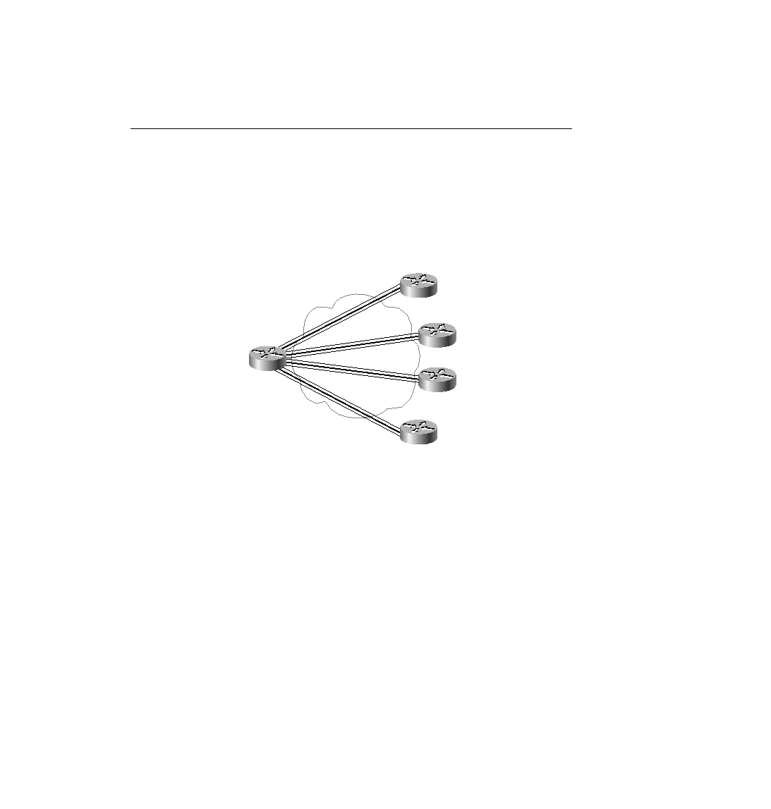
more convenience. Examine Figure 8-10, with Routers D and E added. The service provider
simply states that global DLCI 43 and 44 will be used for these two routers. If these two routers
also have only one PVC to Router A, all the DLCI planning is complete. You know that Router
D and Router E will use DLCI 40 to reach Router A, and that Router A will use DLCI 43 to
reach Router D and DLCI 44 to reach Router E.
otherwise stated. One practical way to determine whether the diagram lists the local DLCIs or
the global DLCI convention is this: If two VCs terminate at a DTE and a single DLCI is shown,
then it probably represents the global DLCI convention. If one DLCI is shown per VC, then it
is depicting local DLCI addressing.
over Frame Relay: