|
|

This chapter describes how to configure the Asynchronous Transfer Mode (ATM) interface in the Cisco 7000 series router. It explains the steps necessary to configure the ATM interface processor (AIP), permanent virtual circuits (PVCs), and switched virtual circuits (SVCs). It also describes how to monitor and maintain the ATM interface. For a complete description of the commands in this chapters, refer to the "ATM Configuration Commands" chapter of the Router Products Command Reference publication.
ATM is a cell-switching and multiplexing technology designed to combine the benefits of circuit switching (constant transmission delay and guaranteed capacity) with those of packet switching (flexibility and efficiency for intermittent traffic).
Cisco's AIP provides a single ATM network interface for the Cisco 7000 series router. Network interfaces for the Cisco 7000 reside on modular interface processors, which provide a direct connection between the high-speed Cisco Extended Bus (CxBus) and the external networks. The maximum number of AIPs that the Cisco 7000 supports depends on the bandwidth configured. The total bandwidth through all the AIPs in the system should be limited to 200 Mbps full duplex (two TAXI interfaces, or one SONET and one E3, or one SONET and one lightly used SONET, or five E3s).
For a complete description of the Cisco 7000 and AIP, refer to the Cisco 7000 Hardware Installation and Maintenance publication. The AIP is compatible with any Cisco 7000 that is running Internetwork Operating System (IOS) Release 10 or later.
ATM is a connection-oriented environment. All traffic to or from an ATM network is prefaced with a virtual path identifier (VPI) and virtual channel identifier (VCI). A VPI/VCI pair is considered a single virtual circuit. Each virtual circuit is a private connection to another node on the ATM network. Each virtual circuit is treated as a point-to-point mechanism to another router or host and is capable of supporting bidirectional traffic.
Each ATM node is required to establish a separate connection to every other node in the ATM network that it wishes to communicate with. All such connections are established using a PVC or an SVC with an ATM signaling mechanism. This signaling is based on the ATM Forum UNI Specification V3.0.
Each virtual circuit is considered a complete and separate link to a destination node. Users can encapsulate data as they see fit across the connection. The ATM network disregards the contents of the data. The only requirement is that data be sent to the AIP card in a manner that follows the specific ATM adaptation layer (AAL) format.
An AAL defines the conversion of user information into cells. That is, it segments upper-layer information into cells at the transmitter and reassembles them at the receiver. AAL1 and AAL2 handle isochronous traffic, such as voice and video, and are not relevant to the router. AAL3/4 and AAL5 support data communications; that is, they segment and reassemble packets. IOS Release 10.2 supports both AAL3/4 and AAL5.
An ATM connection is simply used to transfer raw bits of information to a destination router/host. The ATM router takes the common part convergence sublayer (CPCS) frame, carves it up into 53-byte cells and sends these cells to the destination router or host for reassembly. Forty-eight bytes of each cell are used for the CPCS data; the remaining 5 bytes are used for cell routing. The 5-byte cell header contains the destination VPI/VCI, payload type, cell loss priority (CLP), and header error control.
The ATM network is actually considered a local-area network (LAN) with high bandwidth availability. Each end node in the ATM network is a host on a specific subnet. All end nodes wishing to communicate with each other must be within the same subnet in the network.
Unlike a LAN, which is connectionless, ATM requires certain features to provide a LAN environment to the users. One such feature is broadcast capability. Protocols wishing to broadcast packets to all stations in a subnet must be allowed to do so with a single call to Layer 2. In order to support broadcasting, the router allows the user to specify a particular virtual circuit as a broadcast virtual circuit. When the protocol passes a packet with a broadcast address to the drivers, the packet is duplicated and sent to each virtual circuit marked as a broadcast virtual circuit. This method is known as pseudobroadcasting.
The AIP supports the following features:
All ATM interfaces are full duplex. You must use the appropriate ATM interface cable to connect the AIP with an external ATM network. Refer to the Asynchronous Transfer Mode Interface Processor (AIP) Installation and Configuration publication for descriptions of ATM connectors.
The AIP provides an interface to ATM switching fabrics for transmitting and receiving data at rates of up to 155 Mbps bidirectionally; the actual rate is determined by the physical layer interface module (PLIM). The PLIM contains the interface to the ATM cable. The AIP can support PLIMs that connect to the following physical layers:
For wide-area networking, ATM is currently being standardized for use in Broadband Integrated Services Digital Networks (BISDNs) by the International Telecommunication Union Telecommunication Standardization Sector (ITU-T) and the American National Standards Institute (ANSI). BISDN supports rates from E3 (34 Mbps) to multiple gigabits per second (gbps).
The AIP microcode is a software image that provides card-specific software instructions. An onboard ROM component contains the default AIP microcode. The Cisco 7000 supports downloadable microcode, which enables you to upgrade microcode versions by loading new microcode images onto the route processor (RP), storing them in Flash memory, and instructing the AIP to load an image from Flash memory instead of the default ROM image. You can store multiple images for an interface type and instruct the system to load any one of them or the default ROM image with a configuration command. All processor modules of the same type will load the same microcode image from either the default ROM image or from a single image stored in Flash memory.
Although multiple microcode versions for a specific interface type can be stored concurrently in Flash memory, only one image can load at startup. The show controller cxbus command displays the currently loaded and running microcode version for the switch processor (SP) and for each IP. The write terminal command shows the current system instructions for loading microcode at startup.
For a complete description of microcode and downloading procedures, refer to the Asynchronous Transfer Mode Interface Processor (AIP) Installation and Configuration publication.
A virtual circuit is a point-to-point connection between remote hosts and routers. A virtual circuit is established for each ATM end node with which the router communicates. The characteristics of the virtual circuit are established when the virtual circuit is created and include the following:
Each virtual circuit supports the following router functions:
By default, fast switching is enabled on all AIP interfaces. These switching features can be turned off with interface configuration commands. Autonomous switching must be explicitly enabled per interface.
To configure ATM, complete the tasks in the following sections. The first two tasks are required, and then you must configure at least one PVC or SVC. The virtual circuit options you configure must match in three places: on the router, on the ATM switch, and at the remote end of the PVC or SVC connection.
See the end of this chapter for configuration examples.
This section describes how to begin configuring the AIP. The Cisco 7000 identifies an interface address by its slot number (slots 0 to 4) and port number in the format slot/port. Because each AIP contains a single ATM interface, the port number is always 0. For example, the slot/port address of an ATM interface on an AIP installed in slot 1 is 1/0.
To begin to configure the AIP, start the following task in privileged EXEC mode:
| Task | Command |
|---|---|
| Step 1 At the privileged EXEC prompt, enter configuration mode from the terminal. | configure1 [terminal] <CR> |
| Step 2 Specify an AIP interface. | interface atm slot/02 |
Step 3 If IP routing is enabled on the system, optionally assign a source IP address and subnet mask to the interface. | ip address ip-address mask3 |
To enable the AIP, perform the following task in interface configuration mode:
| Task | Command |
|---|---|
| Change the shutdown state to up and enable the ATM interface, thereby starting the SAR operation on the interface. | no shutdown1 |
The no shutdown command passes an enable command to the AIP, which then begins segmentation and reassembly (SAR) operations. It also causes the AIP to configure itself based on the previous configuration commands sent.
The AIP requires a rate queue, and therefore the task described in this section is required. A rate queue defines the speed at which individual virtual circuits will transmit data to the remote end. Every virtual circuit must be associated with one rate queue. The AIP supports up to eight different peak rates. The peak rate is the maximum rate, in kilobits per second, at which virtual circuit can transmit. Once attached to this rate queue, the virtual circuit is assumed to have its peak rate set to that of the rate queue.
You can configure each rate queue independently to a portion of the overall bandwidth available on the ATM link. The combined bandwidths of all rate queues should not exceed the total bandwidth available. A warning message is displayed if you attempt to configure the combined rate queues beyond what is available to the AIP. The total bandwidth depends on the PLIM (see the section entitled "AIP Interface Types" earlier in this chapter).
The rate queues are broken into a high (0 through 3) and low (4 through 7) bank. When the rate queues are configured beyond the bandwidth available, the AIP will service the high priority banks until they are empty and then service the low priority banks.
A rate queue has access to only a certain portion of the overall bandwidth available on the network connection. Virtual circuits associated with a rate queue each get a portion of the rate queue bandwidth. The rate queue does not consume more bandwidth than assigned when the rate queue was created. For example, a 10-Mbps rate queue uses a maximum of 10 Mbps on the network connection regardless of how many virtual circuits are associated to the rate queue.
To set a rate queue, perform the following task in interface configuration mode:
| Task | Command |
|---|---|
| Configure the rate queue, which defines the maximum speed at which an individual virtual circuit transmits data to a remote ATM host. | atm rate-queue queue-number speed |
You must create a rate queue before you can create PVCs or SVCs. If all rate queues are unconfigured, a warning message will appear, as follows:
%WARNING:(ATM4/0): All rate queues are disabled
If the combined rates exceed the PLIM rate, a warning message appears, as follows:
%WARNING(ATM4/0): Total rate queue allocation nMbps exceeds maximum of nMbps
You can customize the AIP. The features you can customize have default values that will most likely suit your environment and probably need not be changed. However, you might need to enter configuration commands, depending upon the requirements for your system configuration and the protocols you plan to route on the interface. Perform the task in the following sections if you need to customize the AIP:
Each interface has a default maximum packet size or maximum transmission unit (MTU) size. On the AIP, this number defaults to 4470 bytes; the maximum is 9188 bytes. To set the maximum MTU size, perform the following task in interface configuration mode:
| Task | Command |
|---|---|
| Set the maximum MTU size. | mtu bytes1 |
The default SONET PLIM is STS-3C.To set the SONET PLIM to STM-1, perform the following task in interface configuration mode:
| Task | Command |
|---|---|
| Set the SONET PLIM to STM-1. | atm sonet stm-1 |
To loop all packets back to the AIP instead of the network, perform the following task in interface configuration mode:
| Task | Command |
|---|---|
| Set loopback mode. | loopback plim |
The exception queue is used for reporting ATM events, such as CRC errors. By default, it holds 32 entries; the range is 8 to 256. It is unlikely you will need to configure the exception-queue length; if you do, perform the following task in interface configuration mode:
| Task | Command |
|---|---|
| Set the exception-queue length. | atm exception-queue number |
By default, the ATM interface allows the maximum of 4096 virtual circuits. However, you can configure a lower number, thereby limiting the number of virtual circuits on which the AIP allows segmentation and reassembly to occur. Limiting the number of virtual circuits does not affect the VPI/VCI of each virtual circuit.
To set the maximum number of virtual circuits supported (including PVCs and SVCs), perform the following task in interface configuration mode:
| Task | Command |
|---|---|
| Limit the number of virtual circuits. | atm maxvc number |
Message identifier (MID) numbers are used by receiving devices to reassemble cells from multiple sources into packets.
To ensure that the message identifiers will be unique at the receiving end and, therefore, that messages can be reassembled correctly, you can limit the number of message identifiers allowed on a virtual circuit and assign different ranges of message identifiers to different PVCs.
To limit the number of message identifier numbers allowed on each virtual circuit and to assign different ranges of message identifiers to different PVCs, complete the following tasks in interface configuration mode:
| Task | Command |
|---|---|
| Limit the number of message identifiers allowed per virtual circuit. | atm mid-per-vc maximum |
| Limit the range of message identifiers used on a PVC. | atm pvc vcd vpi vci aal-encap midlow midhigh |
The maximum number of message identifiers per virtual circuit is set at 16 by default, and may take only the values 16, 32, 64, 128, 256, 512, or 1024.
The default value for both midlow and midhigh is zero.
The raw queue is used for raw ATM cells, which include operation and maintenance (OAM) and Interim Local Management Interface (ILMI) cells. ILMI is a means of passing information to the router including information about virtual connections and addresses.
The raw-queue size is in the range of 8 to 256 cells; the default is 32 cells. To set the raw-queue size, perform the following task in interface configuration mode:
| Task | Command |
|---|---|
| Set the raw-queue size. | atm rawq-size number |
The number of receive buffers determines the maximum number of reassemblies that the AIP can perform simultaneously. The number of buffers defaults to 256, although it can be in the range from 0 to 512. To set the number of receive buffers, perform the following task in interface configuration mode:
| Task | Command |
|---|---|
| Set the number of receive buffers. | atm rxbuff number |
The number of transmit buffers determines the maximum number of fragmentations that the AIP can perform simultaneously. The number of buffers defaults to 256, although it can be in the range from 0 to 512. To set the number of transmit buffers, perform the following task in interface configuration mode:
| Task | Command |
|---|---|
| Set the number of transmit buffers. | atm txbuff number |
By default, the AIP supports 1024 VCIs per VPI. This value can be in the range of 1 to 4096.This value controls the memory allocation in the AIP to deal with the VCI table. It defines only the maximum number of VCIs to support per VPI; it does not bound the VCI numbers.
To set the maximum number of VCIs to support per VPI, perform the following task in interface configuration mode:
| Task | Command |
|---|---|
| Set the number of VCIs per VPI. | atm vc-per-vp number |
The VP filter allows you to specify which VPI or range of VPIs will be used for AAL3/4 processing. The default value of the AIP's VP filter register is 0x7B. To set the AIP VP filter register, perform the following task in interface configuration mode:
| Task | Command |
|---|---|
| Set the VP filter register. | atm vp-filter hexvalue |
By default, the AIP expects the ATM switch to provide transmit clocking. To specify that the AIP generate the transmit clock internally for SONET and E3 PLIM operation, perform the following task in interface configuration mode:
| Task | Command |
|---|---|
| Specify that the AIP generate the transmit clock internally. | atm clock internal |
If you are going to use a permanent virtual circuit (PVC), the PVC must be configured into both the router and the ATM switch. PVCs remain active until the circuit is removed from either configuration.
All virtual circuit characteristics listed in the section "Virtual Circuits" earlier in this chapter apply to these PVCs. When a PVC is configured, all the configuration options are passed on to the AIP. These PVCs are writable into the nonvolatile RAM (NVRAM) as part of the RP configuration and are used when the RP image is reloaded.
Some ATM switches might have point-to-multipoint PVCs that do the equivalent of broadcasting. If a point-to-multipoint PVC exists, then that PVC can be used as the sole broadcast PVC for all multicast requests.
To configure a PVC, you must perform the tasks in the following sections:
To create a PVC on the AIP interface, perform the following task in interface configuration mode:
| Task | Command |
|---|---|
| Create a PVC. | atm pvc vcd vpi vci aal-encap [peak] [average] [burst] |
When you create a PVC, you create a virtual circuit descriptor (VCD) and attach it to the VPI and VCI. A VCD is an AIP-specific mechanism that identifies to the AIP which VPI/VCI to use for a particular packet. The AIP requires this feature to manage the packets, for transmission. The number chosen for the VCD is independent of the VPI/VCI used.
When you create a PVC, you also specify the AAL and encapsulation. A rate queue is used that matches the peak and average rate selections, which are specified in kilobits per second. Omitting a peak and average value causes the PVC to be connected to the highest bandwidth rate queue available. In this case, the peak and average values are equal.
See examples of PVC configurations in the section "ATM Configuration Examples" at the end of this chapter.
The ATM interface supports a static mapping scheme that identifies the ATM address of remote hosts or routers. This address is specified as a virtual circuit descriptor (VCD) for a PVC (or an NSAP address for SVC operation). This section describes how to map a PVC to an address, which is a required task if you are configuring a PVC.
You enter mapping commands as groups. You first create a map list and then associate it with an interface. Begin the following tasks in global configuration mode:
| Task | Command |
|---|---|
| Step 1 Create a map list by naming it, and enter map-list configuration mode. | map-list name |
| Step 2 Associate a protocol and address to a specific virtual circuit. | protocol protocol-address atm-vc vcd [broadcast] |
| Step 3 Associate a protocol and address to a different virtual circuit. | protocol protocol-address atm-vc vcd [broadcast] |
| Step 4 Specify an ATM interface and enter interface configuration mode. | interface atm slot/port1 |
| Step 5 Associate a map list to an interface. | map-group name |
A map list can contain multiple map entries, as steps 2 and 3 in the preceding task table illustrate. The broadcast keyword specifies that this map entry is to be used when the corresponding protocol wants to send broadcast packets to the interface (for example, any network routing protocol updates). If you do not specify broadcast, the ATM software is prevented from sending routing protocol updates to the remote hosts.
Step 5 illustrates that when the map list is complete, the list is then associated with an ATM interface by using the same name argument.
You can create multiple map lists, but only one map list can be associated with an interface. Different map lists can be associated with different interfaces. See the examples at the end of this chapter.
ATM switched virtual circuit (SVC) service operates much like X.25 SVC service, although ATM allows much higher throughput. Virtual circuits are created and released dynamically, providing user bandwidth on demand. This service requires a signaling protocol between the router and the switch.
The ATM signaling software provides a method of dynamically establishing, maintaining, and clearing ATM connections at the User-Network Interface (UNI). The ATM signaling software conforms to ATM Forum UNI 3.0.
In UNI mode, the user is the router and the network is an ATM switch. This is an important distinction. The Cisco router does not perform ATM-level routing; the ATM switch does the ATM routing. The router is used primarily as a LAN interconnection device. The router is viewed as the user at the end of the circuit, and the ATM switch is viewed as the network.
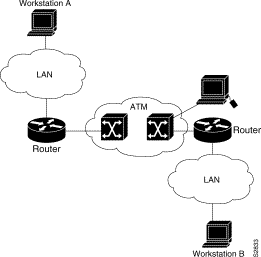
Figure 7-1 illustrates the router position in a basic ATM environment. The router is used primarily to interconnect LANs via an ATM network. The workstation connected directly to the destination ATM switch illustrates that you can connect not only routers to ATM switches, but also any computer with an ATM interface that conforms to ATM Forum UNI specification.
You must complete the tasks in the following sections if you are going to use SVCs:
The tasks in the following sections are optional SVC tasks for customizing your network. These tasks are considered advanced; the default values are almost always adequate. You should not have to perform these tasks unless you really need to customize your particular SVC connection.
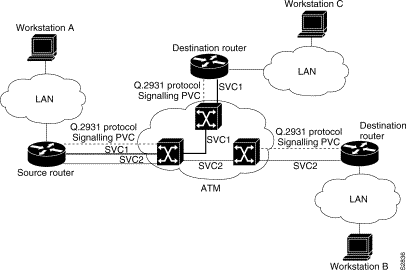
Unlike X.25 service, which uses in-band signaling (connection establishment done on the same circuit as data transfer), ATM uses out-of-band signaling. This means that one dedicated PVC exists between the router and the ATM switch, over which all SVC call establishment and call termination requests flow. After the call is established, data transfer occurs over the SVC, from router to router. The signaling that accomplishes the call setup and tear down is called Layer 3 signaling or Q.2931 protocol.
The out-of-band signaling method means that an SVC requires that a PVC be configured. Figure 7-2 illustrates a signaling PVC from the source router to the ATM switch used to set up two SVCs. This is a fully meshed network; workstations A, B, and C all can communicate with each other.
To configure the signaling PVC for all SVC connections, perform the following task in interface configuration mode:
| Task | Command |
|---|---|
| Configure the signaling PVC for an interface that uses SVCs. | atm pvc vcd vpi vci qsaal |
See the section "Example of SVCs in a Fully Meshed Network" at the end of this chapter for a sample ATM signaling configuration.
Every ATM interface involved with signaling must be configured with an NSAP address. The NSAP address is the ATM address of the interface and must be unique across the network.
ATM NSAP addresses have a fixed length of 40 hexadecimal digits. You must configure the complete address in hexadecimal format; that is, each digit entered represents a hexadecimal digit. To represent the complete NSAP address, you must enter 40 hexadecimal digits in the following format:
XX.XXXX.XX.XXXXXX.XXXX.XXXX.XXXX.XXXX.XXXX.XXXX.XX
There is no default NSAP address for the interface, which is why you must configure the NSAP address for SVCs. To set the ATM interface's source NSAP address, perform the following task in interface configuration mode:
| Task | Command |
|---|---|
| Configure the ATM NSAP address for an interface. | atm nsap-address nsap-address |
The following example assigns NSAP address AB.CDEF.01.234567.890A.BCDE.F012.3456.7890.1234.12 to ATM interface 4/0:
interface ATM4/0
atm nsap-address AB.CDEF.01.234567.890A.BCDE.F012.3456.7890.1234.12
You can display the ATM address for the interface by executing the show interface atm slot /0 command.
The tasks in this section are optional and advanced. The ATM signaling software tells the AIP card and the ATM switch how much traffic the source router will be sending. It provides this information in the form of quality of service (QOS) parameters. (These parameters have default values.) The ATM switch in turn sends these parameters as requested by the source to the ATM destination node. If the destination cannot provide such capacity levels, the call fails. This is a single attempt to match QOS parameters.
This section describes how to change QOS values to customize your SVC connection. The individual tasks that separately specify peak, sustainable, or burst values for an SVC are analogous to the peak, average, and burst values defined when you create a PVC.
Forward commands are from the source router to the destination router. Backward commands are from the destination router to the source router.
Most of the SVC QOS parameters include the concept of cell loss priority (CLP). CLP defines two levels of cell importance:
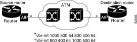
Figure 7-3 illustrates a source and a destination router implementing QOS settings that correspond end-to-end. The value for the forward command at the source router corresponds to the value for the backward command at the destination router.
To change the QOS values from their default values, perform one or more of the following tasks in map-class configuration mode:
The Service Specific Connection Oriented Protocol (SSCOP) resides in the service specific convergence sublayer (SSCS) of the ATM adaptation layer (AAL). SSCOP is used to transfer variable-length service data units (SDUs) between users of SSCOP. SSCOP provides for the recovery of lost or corrupted SDUs.
The poll timer controls the maximum time between transmission of a POLL PDU when SD or SDP PDUs are queued for transmission or are outstanding pending acknowledgments. To change the poll timer from the default value of 10 seconds, perform the following task in interface configuration mode:
| Task | Command |
|---|---|
| Set the poll timer. | sscop poll-timer seconds |
The keepalive timer controls the maximum time between transmission of a POLL PDU when no SD or SDP PDUs are queued for transmission or are outstanding pending acknowledgments. To change the keepalive timer from the default value of 30 seconds, perform the following task in interface configuration mode:
| Task | Command |
|---|---|
| Set the keepalive timer. | sscop keepalive-timer seconds |
The connection control timer determines the time between transmission of BGN, END, or RS PDUs as long as an acknowledgment has not been received. Connection control performs the establishment, release, and resynchronization of an SSCOP connection.
To change the connection control timer from the default value of 10 seconds, perform the following task in interface configuration mode:
| Task | Command |
|---|---|
| Set the connection control timer. | sscop cc-timer seconds |
To change the retry count of the connection control timer from the default value of 10, perform the following task in interface configuration mode:
| Task | Command |
|---|---|
| Set the number of times that SSCOP will retry to transmit BGN, END, or RS PDUs when they have not been acknowledged. | sscop max-cc retries |
A transmit window controls how many packets can be transmitted before an acknowledgment is required. To change the transmitter's window from the default value of 7, perform the following task in interface configuration mode:
| Task | Command |
|---|---|
| Set the transmitter's window. | sscop send-window packets |
A receive window controls how many packets can be received before an acknowledgment is required. To change the receiver's window from the default value of 7, perform the following task in interface configuration mode:
| Task | Command |
|---|---|
| Set the receiver's window. | sscop rcv-window packets |
Since the AIP does not perform packet-level accounting on a per-VC basis, the interface does not close an idle SVC automatically. You must perform this task in EXEC mode if you want to close a particular SVC:
| Task | Command |
|---|---|
| Close the signaling PVC for an SVC. | atmsig close atmslot/0 vcd |
An AAL defines the conversion of user information into cells. That is, it segments upper-layer information into cells at the transmitter and reassembles them at the receiver. AAL1 and AAL2 handle isochronous traffic, such as voice and video, and are not relevant to the router. AAL3/4 and AAL5 support data communications; that is, they segment and reassemble packets. IOS Release 10.2 supports both AAL3/4 and AAL5.
Our implementation of the AAL3/4 encapsulates each AAL3/4 packet in an SMDS header and trailer. This feature supports both unicast and multicast addressing, and provides subinterfaces for multiple AAL3/4 connections over the same physical interface.
Support for AAL3/4 on an ATM interface requires static mapping of all protocols except IP. However, dynamic routing of IP can coexist with static mapping of other protocols on the same ATM interface.
To configure an ATM interface for SMDS networks, perform the following tasks in interface configuration mode:
The VP filter provides a mechanism for specifying which VPIs (or a range of VPIs) will be used for AAL3/4 processing during datagram reassembly. All other VPIs are mapped to AAL5 processing. For more information about the way the command works and the effect of selecting specific values, refer to the Router Products Command Reference publication.
After configuring the ATM interface for SMDS networks, configure the interface for standard protocol configurations, as needed. For more information about protocol configuration, refer to the relevant chapters of this manual.
For examples of configuring an ATM interface for AAL3/4 support, see the "PVC Examples with AAL3/4 and SMDS Encapsulation" section later in this chapter.
After configuring the new interface, you can display its status. You can also display the current state of the ATM network and connected virtual circuits. To show current virtual circuits and traffic information, perform the following tasks in EXEC mode:
| Task | Command |
|---|---|
| Display ATM-specific information about an ATM interface. | show atm interface atm slot/0 |
| Display the configured list of ATM static maps to remote hosts on an ATM network. | show atm map |
| Display global traffic information to and from all ATM networks connected to the router. Display a list of counters of all ATM traffic on this router. | show atm traffic |
| Display ATM virtual circuit information about all PVCs and SVCs (or a specific virtual circuit). | show atm vc [vcd] |
| Display statistics for the ATM interface. | show interfaces atm slot/01 |
| Display SSCOP details for the ATM interface. | show sscop |
The examples in the following sections illustrate how to configure an ATM interface:
The following example provides a minimal configuration of an ATM interface to support AAL3/4 and SMDS encapsulation; no protocol configuration is shown:
interface atm3/0
atm aal aal3/4
atm smds c140.888.9999
atm vp-filter 0
atm multicast e180.0999.9999
atm pvc 30 0 30 aal34smds
The following example shows how IP dynamic routing might coexist with static routing of another protocol.
interface atm3/0
ip addr 131.108.168.112 255.255.255.0
atm aal aal3/4
atm smds c140.888.9999
atm multicast e180.0999.9999
atm vp-filter 0
atm pvc 30 0 30 aal34smds
map-group atm
appletalk address 10.1
appletalk zone atm
!
map-group atm
atalk 10.2 smds c140.8111.1111 broadcast
This example shows that IP configured as dynamically routed, but that AppleTalk is statically routed. An AppleTalk remote host is configured at address 10.2 and is associated with SMDS address c140.8111.1111.
AAL3/4 associates a protocol address with an SMDS address, as shown in the last line of this example. In contrast, AAL5 static maps associate a protocol address with a PVC number.
The following example creates PVC 5 on ATM interface 3/0. It uses LLC/SNAP encapsulation over AAL5. The interface is at IP address 1.1.1.1 with 1.1.1.5 at the other end of the connection. The static map list named atm declares that the next node is a broadcast point for multicast packets from IP.
interface atm 3/0
ip address 1.1.1.1 255.255.255.0
atm rate-queue 1 100
atm pvc 5 0 10 aal5snap
ip route-cache cbus
map-group atm
map-list atm
ip 1.1.1.5 atm-vc 5 broadcast
The following example is of a typical ATM configuration for a PVC:
interface atm4/0
ip address 131.108.168.112 255.255.255.0
map-group atm
atm rate-queue 1 100
atm maxvc 512
atm pvc 1 1 1 aal5snap
atm pvc 2 2 2 aal5snap
atm pvc 6 6 6 aal5snap
atm pvc 7 7 7 aal5snap
decnet cost 1
clns router iso-igrp comet
!
router iso-igrp comet
net 47.0004.0001.0000.0c00.6666.00
!
router igrp 109
network 131.108.0.0
!
ip domain-name CISCO.COM
!
map-list atm
ip 131.108.168.110 atm-vc 1 broadcast
clns 47.0004.0001.0000.0c00.6e26.00 atm-vc 6 broadcast
decnet 10.1 atm-vc 2 broadcast
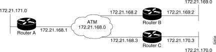
Figure 7-4 illustrates a fully meshed network. The configurations for Routers A, B, and C follow the figure. In this example, the routers are configured to use PVCs. Fully meshed indicates that any workstation can communicate with any other workstation. Note that the two map-list statements configured in Router A identify the ATM addresses of Routers B and C. The two map-list statements in Router B identify the ATM addresses of Routers A and C. The two map list statements in Router C identify the ATM addresses of Routers A and B.
ip routing
!
interface atm 4/0
ip address 131.108.168.1 255.255.255.0
atm rate-queue 1 100
atm pvc 1 0 10 aal5snap
atm pvc 2 0 20 aal5snap
map-group test-a
!
map-list test-a
ip 131.108.168.2 atm-vc 1 broadcast
ip 131.108.168.3 atm-vc 2 broadcast
ip routing
!
interface atm 2/0
ip address 131.108.168.2 255.255.255.0
atm rate-queue 1 100
atm pvc 1 0 20 aal5snap
atm pvc 2 0 21 aal5snap
map-group test-b
!
map-list test-b
ip 131.108.168.1 atm-vc 1 broadcast
ip 131.108.168.3 atm-vc 2 broadcast
ip routing
!
interface atm 4/0
ip address 131.108.168.3 255.255.255.0
atm rate-queue 1 100
atm pvc 2 0 21 aal5snap
atm pvc 4 0 22 aal5snap
map-group test-c
!
map-list test-c
ip 131.108.168.1 atm-vc 2 broadcast
ip 131.108.168.2 atm-vc 4 broadcast
The following example is also a configuration for the fully meshed network shown in Figure 7-4, but this example uses SVCs. PVC 1 is the signaling PVC.
interface atm 4/0
ip address 131.108.168.1 255.255.255.0
map-group atm
atm nsap-address AB.CDEF.01.234567.890A.BCDE.F012.3456.7890.1234.12
atm rate-queue 1 100
atm maxvc 1024
atm pvc 1 0 5 qsaal
!
map-list atm
ip 131.108.168.2 atm-nsap BC.CDEF.01.234567.890A.BCDE.F012.3456.7890.1334.13
ip 131.108.168.3 atm-nsap BC.CDEF.01.234567.890A.BCDE.F012.3456.7890.1224.12
interface atm 2/0
ip address 131.108.168.2 255.255.255.0
map-group atm
atm nsap-address BC.CDEF.01.234567.890A.BCDE.F012.3456.7890.1334.13
atm rate-queue 1 100
atm maxvc 1024
atm pvc 1 0 5 qsaal
!
map-list atm
ip 131.108.168.1 atm-nsap AB.CDEF.01.234567.890A.BCDE.F012.3456.7890.1234.12
ip 131.108.168.3 atm-nsap BC.CDEF.01.234567.890A.BCDE.F012.3456.7890.1224.12
interface atm 4/0
ip address 131.108.168.3 255.255.255.0
map-group atm
atm nsap-address BC.CDEF.01.234567.890A.BCDE.F012.3456.7890.1224.12
atm rate-queue 1 100
atm maxvc 1024
atm pvc 1 0 5 qsaal
!
map-list atm
ip 131.108.168.1 atm-nsap AB.CDEF.01.234567.890A.BCDE.F012.3456.7890.1234.12
ip 131.108.168.2 atm-nsap BC.CDEF.01.234567.890A.BCDE.F012.3456.7890.1334.13
|
|