|
|

Table Of Contents
Defining the VLAN Encapsulation Format
Assigning an IP Address to a Network Interface
Example of IP Routing over IEEE 802.1Q
InterVLAN Routing and 802.1Q Trunking
802.1Q Configuration on the Router for Cisco IOS Versions Earlier than 12.1(3)T
IEEE 802.1Q Configuration
This chapter describes:
•
InterVLAN Routing and 802.1Q Trunking
IP Routing over IEEE 802.1Q
This section provides procedures for configuring protocols supported with IEEE 802.1Q encapsulation. The basic process is the same, regardless of the protocol. The process involves the following:
•
•
•
•
To route IP over IEEE 802.1Q between VLANs, you need to customize the subinterface to create the environment in which it will be used. Perform these tasks in the order in which they appear:
•
•
The IEEE 802.1Q protocol is used to interconnect multiple switches and routers and to define VLAN topologies.
Note
For complete descriptions of the VLAN commands used in this section, refer to the "Cisco IOS Switching Commands" chapter in the Cisco IOS Switching Services Command Reference. For descriptions of other commands that appear in this section, you can either use the command reference master index or search online.
Enabling IP Routing
IP routing is automatically enabled in Cisco routers. To reenable IP routing if it has been disabled, use the following command in global configuration mode:
Router(config)#ip routingOnce you have IP routing enabled on the router, you can customize the characteristics to suit your environment. If necessary, refer to the IP configuration chapters in the Cisco IOS IP and IP Routing Configuration Guide for guidelines on configuring IP.
Defining the VLAN Encapsulation Format
To define the encapsulation format as IEEE 802.1Q, use the following commands in interface configuration mode.
Step 1
interface FastEthernet
slot/port.subinterface-number 1
Specify the subinterface on which IEEE 802.1Q will be used.
Step 2
encapsulation dot1q vlanidDefine the encapsulation format as IEEE 802.1Q and specifies the VLAN identifier.
1 If the router supports only port numbers, and not slot numbers, the format for this command is
interface fastethernet port.subinterface-number
Assigning an IP Address to a Network Interface
An interface can have one primary IP address. To assign a primary IP address and a network mask to a network interface, use the following command in interface configuration mode.
A mask identifies the bits that denote the network number in an IP address. When you use a mask to subnet a network, that mask is referred to as a subnet mask.
Example of IP Routing over IEEE 802.1Q
This configuration example shows IP being routed on VLAN 101:
!ip routing!interface fastethernet 0/0.101encapsulation dot1q 101ip addr 10.0.0.11 255.0.0.0!VLAN Commands
This section provides an alphabetical listing of useful VLAN commands. All CLI commands used with this feature are documented in the Cisco IOS Release 12.1T (or higher) command reference documents.
InterVLAN Routing and 802.1Q Trunking
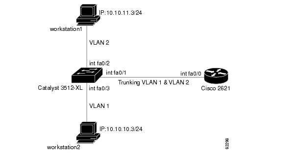
This document provides sample 802.1Q trunking configurations between a Catalyst 3512-XL switch and a Cisco 2600 router; the results of each command are displayed as they are executed. Cisco routers with FastEthernet interfaces, and any Catalyst 2900XL, 3500XL, or 2950 switch can be used in the scenarios presented in this document to obtain the same results.
Trunking is a way to carry traffic from several VLANs over a point-to-point link between the two devices. Ethernet trunking can be implemented by using 802.1Q.
We will create a trunk that carries traffic from two VLANs (VLAN1 and VLAN2) across a single link between a Catalyst 3500 and a Cisco 2600 router. We are using the Cisco 2600 router to do the Inter-VLAN routing between VLAN1 and VLAN2.
Layer 2 switches are not capable of routing or communicating between the VLANs.Therefore, the 10/100 Fast Ethernet interface on the router (FastEthernet 0/0) will support a VLAN, but the 10/100 Fast Ethernet interface on the FESMIC switch (FastEthernet 0/0) will not support a VLAN. For further details on Inter-VLAN routing, refer to the Routing Between Virtual LANs Overview chapter of the "Cisco IOS Switching Services Configuration Guide," release 12.1.
Router Description
For 802.1Q trunking, one VLAN is not tagged. This VLAN is called native VLAN. The native VLAN is used for untagged traffic when the port is in 802.1Q trunking mode. While configuring 802.1Q trunking, keep in mind that the native VLAN must be configured the same on each side of the trunk link. It is a common mistake not to match the native VLANs while configuring 802.1Q trunking between the router and the switch. For details on native VLANs, refer to the IEEE 802.1Q section, of "Bridging Between IEEE 802.1Q VLANs," in New Features in release 12.1(3)T.
In this sample configuration, the native VLAN is VLAN1 by default on both the Cisco 2621 router and the Catalyst 3512XL switch. Depending on your network needs, you might have to use a native VLAN other than the default, VLAN1. Commands in the configurations section of this document describe how to change the native VLAN on the Cisco 2600 router and Catalyst 3500XL switch.
Sample configurations presented in this document can be used on the Cisco 3200 Series router, as it includes at least one 10/100 Fast Ethernet interface. Also, make sure that you are using the Cisco IOS version that supports ISL/802.1Q VLAN trunking.
For more information, see the Cisco Technical Tips Conventions.
Figure 15-1 Network Diagram
Switch Configuration
The following example show the commands that were entered on the 3512XL switch:
Step 1
switch#configure terminalEnter configuration commands, one per line. End with CNTL/Z.switch(config)#hostname 3512xl3512xl(config)#enable password mysecret3512xl(config)#line vty 0 43512xl(config-line)#login3512xl(config-line)#password mysecret3512xl(config-line)#exit3512xl(config)#no logging console3512xl(config)#^ZStep 2
3512xl#configure terminalEnter configuration commands, one per line. End with CNTL/Z.3512xl(config)#int vlan 13512xl(config-if)#ip address 10.10.10.2 255.255.255.03512xl(config-if)#exit3512xl(config)#ip default-gateway 10.10.10.13512xl(config)#endStep 3
In our example, we set the mode to be transparent. Depending on your network, set the VTP Mode accordingly. For details on VTP, refer to "Configuring VTP, VLANs, and VLAN Trunks on Catalyst 2900XL and 3500XL Switches."
3512xl#vlan database3512xl(vlan)#vtp transparentSetting device to VTP TRANSPARENT mode.Step 4
512xl(vlan)#vlan 2VLAN 2 added:Name: VLAN00023512xl(vlan)#exitAPPLY completed.Exiting....Step 5
3512xl#configure terminalEnter configuration commands, one per line. End with CNTL/Z.512xl(config)#int FastEthernet 0/1512xl(config-if)#switchport mode trunkStep 6
512xl(config-if)#switchport trunk encapsulation islor as dot1q
512xl(config-if)#switchport trunk encapsulation dot1qIn case of Cisco 2950 switches, the above two commands are not used. Cisco 2950 switches only support 802.1Q encapsulation, which is configured automatically, when trunking is enabled on the interface by using switchport mode trunk command.
In case of dot1q, make sure that the native VLAN matches across the link. On 3512XL, by default, the native VLAN is 1. Depending on your network needs, you can change the native VLAN to be other than VLAN1, but it is important that you change the native VLAN on the router accordingly. You can change the native VLAN, if needed, by using the following command:
3512xl(config-if)#switchport trunk native vlan <vlanID>Step 7
3512xl(config-if)#switchport trunk allowed vlan all3512xl(config-if)#exitStep 8
3512xl(config)#int FastEthernet 0/23512xl(config-if)#switchport access vlan 23512xl(config-if)#spanning-tree portfast3512xl(config-if)#exitStep 9
3512xl(config)#int FastEthernet 0/33512xl(config-if)#spanning-tree portfast3512xl(config-if)#^ZFor details on why you should enable portfast, refer to "Using Portfast and Other Commands to Fix Workstation Startup Connectivity Delays."
Step 10
3512xl#write memoryBuilding configuration...3512xl#Step 11
3512xl#show running-configBuilding configuration...Current configuration:!version 12.0no service padservice timestamps debug uptimeservice timestamps log uptimeno service password-encryption!hostname 3512xl!no logging consoleenable password mysecret!ip subnet-zero!interface FastEthernet0/1switchport mode trunkIf 802.1Q is configured, you will instead see the following output under interface FastEthernet 0/1:
interface FastEthernet0/1switchport trunk encapsulation dot1qswitchport mode trunk!interface FastEthernet0/2switchport access vlan 2spanning-tree portfast!interface FastEthernet0/3spanning-tree portfast!interface FastEthernet0/4!interface FastEthernet0/5!interface VLAN1ip address 10.10.10.2 255.255.255.0no ip directed-broadcastno ip route-cache!ip default-gateway 10.10.10.1!line con 0transport input nonestopbits 1line vty 0 4password mysecretloginline vty 5 15login!endRouter Configuration
The following examples show the commands that were entered on the Cisco 2600 router.
Step 1
Router#configure terminalEnter configuration commands, one per line. End with CNTL/Z.Router(config)#hostname c2600c2600(config)#enable password mysecretc2600(config)#line vty 0 4c2600(config-line)#loginc2600(config-line)#password mysecretc2600(config-line)#exitc2600(config)#no logging consolec2600(config)#^Zc2600#configure terminalStep 2
c2600(config)#int FastEthernet 0/0c2600(config-if)#no shutc2600(config-if)#exitStep 3
c2600(config)#int FastEthernet 0/0.1Step 4
c2600(config-subif)#encapsulation isl 1or as dot1q. In case of dot1q, you need to make sure that the native VLAN matches across the link. On 3512XL, by default, the native VLAN is 1. On the router, configure VLAN1 as the native VLAN.
c2600(config-subif)#encapsulation dot1Q 1 nativeOn the switch, if you have a native VLAN other than VLAN1, on the router, configure the same VLAN to be the native VLAN, by using the above command.
The following example configures 802.1Q trunking on the router.
Step 1
c2600(config-subif)#ip address 10.10.10.1 255.255.255.0c2600(config-subif)#exitStep 2
c2600(config)#int FastEthernet 0/0.2Step 3
c2600(config-subif)#encapsulation isl 2or as dot1q:
c2600(config-subif)#encapsulation dot1Q 2Step 4
c2600(config-subif)#ip address 10.10.11.1 255.255.255.0c2600(config-subif)#exitc2600(config)#^ZStep 5
c2600#write memoryBuilding configuration...[OK]c2600#To make this setup work, and to successfully ping between workstation1 and workstation2, make sure that the default gateways on the workstations are setup properly. For workstation1, the default gateway should be 10.10.11.1 and for workstation2, the default gateway should be 10.10.10.1. For details on how to set the default gateways on the workstations, refer to their respective sections in this document.
802.1Q Configuration on the Router for Cisco IOS Versions Earlier than 12.1(3)T
As described earlier in this document, while configuring 802.1Q trunking it is very important to match the native VLAN across the link. In the Cisco IOS software versions earlier than 12.1(3)T, you cannot define the native VLAN explicitly, as the encapsulation dot1Q 1 native command under the sub-interface is not available.
In the earlier Cisco IOS versions, it is important not to configure VLAN1 interface as a sub-interface. The router then expects a tag dot1q frame on VLAN1 and the switch is not expecting a tag on VLAN1. As a result, no traffic will pass between VLAN1 on the switch and the router.
Use the following steps to configure the Cisco 2600 router:
Step 1
Router#configure terminalRouter(config)#hostname c2600c2600(config)#enable password mysecretc2600(config)#line vty 0 4c2600(config-line)#login;c2600(config-line)#password mysecretc2600(config-line)#exitc2600(config)#no logging consoleStep 2
c2600(config)#int FastEthernet 0/0c2600(config-if)#no shutNote that the IP address for VLAN1 is configured on the main interface, and no encapsulation for VLAN1 will be done under the sub-interface.
c2600(config-if)#ip address 10.10.10.1 255.255.255.0c2600(config-if)#exitStep 3
c2600(config)#int FastEthernet 0/0.2c2600(config-subif)#encapsulation dot1Q 2Step 4
c2600(config-subif)#ip address 10.10.11.1 255.255.255.0c2600(config-subif)#exitc2600(config)#^ZStep 5
c2600#write memoryBuilding configuration...[OK]c2600#To successfully ping between workstation1 and workstation2, you need to make sure that the default gateways on the workstations are setup properly. For workstation1, the default gateway should be 10.10.11.1, and for workstation2, the default gateway should be 10.10.10.1. For details on how to set the default gateways on the workstations, refer to thei respective sections in this document.
debug and show Commands
Use the show int {FastEthernet} command to check the administrative and operational status of the port. It is also used to make sure that the native VLAN matches on both sides of the trunk. The native VLAN is used for untagged traffic when the port is in 802.1Q trunking mode.
3512xl#show int FastEthernet 0/1 switchportName: Fa0/1Switchport: EnabledAdministrative mode: trunkOperational Mode: trunkAdministrative Trunking Encapsulation: islOperational Trunking Encapsulation: islNegotiation of Trunking: DisabledAccess Mode VLAN: 0 ((Inactive))Trunking Native Mode VLAN: 1 (default)Trunking VLANs Enabled: ALLTrunking VLANs Active: 1,2Pruning VLANs Enabled: 2-1001Priority for untagged frames: 0Override vlan tag priority: FALSEVoice VLAN: noneAppliance trust: noneFor 802.1Q trunking, the output of the above command changes as follows:
Router#show int FastEthernet 0/1 switchportName: Fa0/1Switchport: EnabledAdministrative mode: trunkOperational Mode: trunkAdministrative Trunking Encapsulation: dot1qOperational Trunking Encapsulation: dot1qNegotiation of Trunking: DisabledAccess Mode VLAN: 0 ((Inactive))Trunking Native Mode VLAN: 1 (default)Trunking VLANs Enabled: ALLTrunking VLANs Active: 1,2Pruning VLANs Enabled: 2-1001Priority for untagged frames: 0Override vlan tag priority: FALSEVoice VLAN: noneshow vlans Command
Use the show vlans command on the MARC to verify that the 10/100 Fast Ethernet interface (port) belongs to the correct VLAN. In our example, only interface FastEthernet 0/0 belongs to VLAN2. The rest are members of VLAN1.
3512xl#show vlansVLAN Name Status Ports---- ------------------------- -------- -------------------------------1 default active Fa0/3, Fa0/42 VLAN0002 active Fa0/01002 fddi-default active1003 token-ring-default active1004 fddinet-default active1005 trnet-default active...(output suppressed)show vlan-switch Command
Use the show vlan-switch command on the FESMIC interfaces to verify that the interface (port) belongs to the correct VLAN.
virgoa1#sh vlan-switchVLAN Name Status Ports---- -------------------------------- --------- -----------------------1 default active2 VLAN0002 active Fa3/0, Fa3/13 VLAN0003 active4 VLAN0004 active5 VLAN0005 active Fa3/36 VLAN0006 active1002 fddi-default active1003 token-ring-default active1004 fddinet-default active1005 trnet-default activeVLAN Type SAID MTU Parent RingNo BridgeNo Stp BrdgMode Trans1 Trans2---- ----- ---------- ----- ------ ------ -------- ---- -------- ------ ------1 enet 100001 1500 - - - - - 1002 10032 enet 100002 1500 - - - - - 0 03 enet 100003 1500 - - - - - 0 04 enet 100004 1500 - - - - - 0 05 enet 100005 1500 - - - - - 0 06 enet 100006 1500 - - - - - 0 01002 fddi 101002 1500 - - - - - 1 1003VLAN Type SAID MTU Parent RingNo BridgeNo Stp BrdgMode Trans1 Trans2---- ----- ---------- ----- ------ ------ -------- ---- -------- ------ ------1003 tr 101003 1500 1005 0 - - srb 1 10021004 fdnet 101004 1500 - - 1 ibm - 0 01005 trnet 101005 1500 - - 1 ibm - 0 0show vtp status Command
This command is used to check the VLAN trunking protocol (VTP) configuration on the switch. In our example, we have used transparent mode. The correct VTP mode depends on the topology of your network. For details on VTP, refer to Configuring VTP, VLANs, and VLAN Trunks on Catalyst 2900XL and 3500XL Switches.
3512xl#show vtp statusVTP Version : 2Configuration Revision : 0Maximum VLANs supported locally : 254Number of existing VLANs : 6VTP Operating Mode : TransparentVTP Domain Name :VTP Pruning Mode : DisabledVTP V2 Mode : DisabledVTP Traps Generation : DisabledMD5 digest : 0xC3 0x71 0xF9 0x77 0x2B 0xAC 0x5C 0x97Configuration last modified by 0.0.0.0 at 0-0-00 00:00:00show vlan Command
This command tells you what L2 or L3 information is configured for each VLAN.
c2600#show vlanVirtual LAN ID: 1 (Inter Switch Link Encapsulation)vLAN Trunk Interface: FastEthernet0/0.1Protocols Configured: Address: Received: Transmitted:IP 10.10.10.1 40 38Virtual LAN ID: 2 (Inter Switch Link Encapsulation)vLAN Trunk Interface: FastEthernet0/0.2Protocols Configured: Address: Received: Transmitted:IP 10.10.11.1 9 9For 802.1Q trunking, the output of the above command changes as follows:
c2600#show vlanVirtual LAN ID: 1 (IEEE 802.1Q Encapsulation)vLAN Trunk Interface: FastEthernet0/0.1This is configured as native Vlan for the following interface(s): FastEthernet0/0
Protocols Configured: Address: Received: Transmitted:IP 10.10.10.1 0 2Virtual LAN ID: 2 (IEEE 802.1Q Encapsulation)vLAN Trunk Interface: FastEthernet0/0.2Protocols Configured: Address: Received: Transmitted:IP 10.10.11.1 42 19For 802.1Q trunking, with Cisco IOS versions earlier then 12.1(3)T, the output of the command changes as follows:
c2600#show vlanVirtual LAN ID: 2 (IEEE 802.1Q Encapsulation)vLAN Trunk Interface: FastEthernet0/0.2Protocols Configured: Address: Received: Transmitted:IP 10.10.11.1 6 4No IEEE 802.1Q encapsulation is displayed for VLAN1 on any of the sub-interfaces.
show interface Command
Use the show interfaces command to check the administrative and operational status of the interface.
c2600#show interfaces FastEthernet 0/0FastEthernet0/0 is up, line protocol is upHardware is AmdFE, address is 0003.e36f.41e0 (bia 0003.e36f.41e0)MTU 1500 bytes, BW 100000 Kbit, DLY 100 usec,reliability 255/255, txload 1/255, rxload 1/255Encapsulation ARPA, loopback not setKeepalive set (10 sec)Full-duplex, 100Mb/s, 100BaseTX/FXARP type: ARPA, ARP Timeout 04:00:00Last input 00:00:00, output 00:00:07, output hang neverLast clearing of "show interface" counters neverQueueing strategy: fifoOutput queue 0/40, 0 drops; input queue 0/75, 0 drops5 minute input rate 0 bits/sec, 1 packets/sec5 minute output rate 0 bits/sec, 0 packets/sec217 packets input, 12884 bytesReceived 217 broadcasts, 0 runts, 0 giants, 0 throttles0 input errors, 0 CRC, 0 frame, 0 overrun, 0 ignored0 watchdog0 input packets with dribble condition detected45 packets output, 6211 bytes, 0 underruns(0/0/0)0 output errors, 0 collisions, 4 interface resets0 babbles, 0 late collision, 0 deferred0 lost carrier, 0 no carrier0 output buffer failures, 0 output buffers swapped outc2600#show interfaces FastEthernet 0/0.1FastEthernet0/0.1 is up, line protocol is upHardware is AmdFE, address is 0003.e36f.41e0 (bia 0003.e36f.41e0)Internet address is 10.10.10.1/24MTU 1500 bytes, BW 100000 Kbit, DLY 100 usec,reliability 255/255, txload 1/255, rxload 1/255Encapsulation ISL Virtual LAN, Color 1.ARP type: ARPA, ARP Timeout 04:00:00c2600#show interfaces FastEthernet 0/0.2FastEthernet0/0.2 is up, line protocol is upHardware is AmdFE, address is 0003.e36f.41e0 (bia 0003.e36f.41e0)Internet address is 10.10.11.1/24MTU 1500 bytes, BW 100000 Kbit, DLY 100 usec,reliability 255/255, txload 1/255, rxload 1/255Encapsulation ISL Virtual LAN, Color 2.ARP type: ARPA, ARP Timeout 04:00:00For 802.1Q trunking, the output of the above command changes as follows:
c2600#show interfaces FastEthernet 0/0.1FastEthernet0/0.1 is up, line protocol is upHardware is AmdFE, address is 0003.e36f.41e0 (bia 0003.e36f.41e0)Internet address is 10.10.10.1/24MTU 1500 bytes, BW 100000 Kbit, DLY 100 usec,reliability 255/255, txload 1/255, rxload 1/255Encapsulation 802.1Q Virtual LAN, Vlan ID 1.ARP type: ARPA, ARP Timeout 04:00:00c2600#show interfaces FastEthernet 0/0.2FastEthernet0/0.2 is up, line protocol is upHardware is AmdFE, address is 0003.e36f.41e0 (bia 0003.e36f.41e0)Internet address is 10.10.11.1/24MTU 1500 bytes, BW 100000 Kbit, DLY 100 usec,reliability 255/255, txload 1/255, rxload 1/255Encapsulation 802.1Q Virtual LAN, Vlan ID 2.ARP type: ARPA, ARP Timeout 04:00:00
![]()
![]()
![]()
![]()
![]()
![]()
![]()
![]()
Posted: Wed Nov 1 10:33:41 PST 2006
All contents are Copyright © 1992--2006 Cisco Systems, Inc. All rights reserved.
Important Notices and Privacy Statement.